
Electronixity guide
LEDs Explained: How They Work, How to Drive Them, and How Not to Kill Them
A practical guide to LED basics, forward voltage, current limiting, wiring, dimming, thermal management, and fault finding.
You connect a 5 mm red LED straight across a 9 V battery. It flashes very brightly, then goes dark. The plastic body still looks perfect, so you try another one. Same result. The problem was not bad luck. An LED is a diode, and a diode does not set its own current. The battery supplied far more current than the tiny die could survive.
By the end of this guide you will know what happens inside an LED, how to identify its anode and cathode, how to read the useful parts of a datasheet, how to calculate a safe resistor, and when a transistor or constant-current driver is needed. You will also have a method for diagnosing a dark, dim, flickering, or overheated LED circuit.
What an LED Actually Is
Start with the word diode. An LED is a diode that has been made from semiconductor materials that release useful light when current crosses a P-N junction. The light source is the result of the diode physics, not a separate lamp hidden inside the package.
A P-N junction joins P-type semiconductor, where mobile holes are the main carriers, to N-type semiconductor, where electrons are the main carriers. With forward bias applied, electrons and holes are pushed toward the junction. When they recombine, the lost energy can leave as a photon. That process is called electroluminescence.
The semiconductor band gap sets the photon energy. A wider band gap produces a higher-energy photon with a shorter wavelength, which moves the colour toward blue or ultraviolet. A smaller band gap produces a longer wavelength, such as red or infrared. The coloured epoxy lens does not create the colour. It can tint, diffuse, or filter the light, but the semiconductor material determines the emitted wavelength.
| Material | Typical LED use | Typical colour |
|---|---|---|
| AlGaAs | Indicator and infrared emitters | Red to near infrared |
| GaP | Older visible indicators | Green, yellow |
| InGaN | Modern blue, white, and UV dies | Blue to ultraviolet |
| AlGaInP | Efficient visible indicators | Amber, orange, red |
White LEDs are usually blue InGaN LEDs covered by a phosphor. Some blue light passes through while some is converted into a broad yellow-white spectrum. That is why a white LED can have a forward voltage closer to a blue LED than to a red one.
Inside an LED: Anatomy and Symbol
A common 5 mm through-hole LED has an epoxy dome, a reflector cup, a semiconductor die, a fine gold bond wire, and two metal leads. The die sits in the reflector cup, which sends more light forward through the lens. The cup is usually connected to the wider internal post, called the anvil or cathode post.
The fat cathode post also provides a useful thermal path. At a 20 mA indicator current it barely gets warm. In a high-power package, the equivalent thermal path must carry much more heat from the die into an aluminium substrate and then a heatsink.
The circuit symbol is a diode symbol with two arrows pointing outward. The bar marks the cathode, the negative side in normal forward operation. The triangle-like shape seen in some simplified drawings is not the standard LED symbol, so check the bar when reading a schematic.
A water-clear lens gives a narrow, intense beam. It is useful for aiming light or coupling into an optical sensor. A diffused lens scatters light through a wider angle, so it looks more even from the side but less intense along the centre line.
Finding the Polarity: Four Reliable Methods
- Longer leg: on an untrimmed through-hole LED, the longer lead is normally the anode. It stops helping after you cut the leads or buy a pre-trimmed part.
- Flat rim: the small flat spot on the epoxy rim normally marks the cathode side.
- Internal shape: look through a clear body. The larger cup-shaped electrode is normally the cathode. The smaller post connects to the anode.
- Diode mode: put a multimeter in diode-test mode. With the red probe on the anode and black probe on the cathode, a visible LED often glows faintly and the meter displays its forward voltage. This is the dependable method for trimmed leads and many loose parts.
SMD markings vary. A green line, notch, T-mark, or differently shaped corner can indicate the cathode, but there is no universal convention across every package and manufacturer. If the part is not obvious, use its datasheet. A magnifier and a continuity check are faster than guessing on a populated board.
The Numbers That Matter: Reading a Datasheet
You rarely need every page of an LED datasheet. Find the electrical characteristics table, the absolute maximum ratings, the optical table, and the thermal notes. The values below are typical ranges, not universal specifications.
| Parameter | Symbol | Typical value | What it means in practice |
|---|---|---|---|
| Forward voltage | Vf | 1.8–3.4 V | Voltage across the LED at a stated current |
| Forward current | If | 20 mA | Common indicator operating current |
| Absolute maximum current | If(max) | 30 mA | A ceiling, not a target for normal operation |
| Reverse voltage | Vr | About 5 V | Very low compared with a normal rectifier diode |
| Luminous intensity | Iv | mcd | On-axis brightness, not total light output |
| Viewing angle | 2θ½ | 15°–140° | Angle where measured intensity falls to half |
| Peak wavelength | λp | About 400–950 nm | Where the LED’s output peaks |
| Power dissipation | Pd | About 100 mW for indicators | Approximately Vf × If |
Absolute maximum means do not exceed it under the specified conditions. It does not mean the part is designed to run there continuously. A 30 mA maximum LED is usually happier at 5–15 mA, especially inside a warm enclosure. Datasheets may also derate allowable current as ambient temperature rises.
Why You Always Need a Current Limiter
LEDs are current-driven devices. Their forward voltage is a result of the current and temperature, not a convenient setting that the LED enforces. Once the diode reaches its knee, a small voltage increase can cause a large current increase.
Imagine a red LED with a forward voltage near 2.0 V at 20 mA. A 9 V battery does not “push 9 V through the LED” in a controlled way. The LED initially takes current until its junction voltage rises, but nothing in the battery-and-LED loop limits the next increment. The die heats, its forward voltage usually falls, and the lower voltage encourages still more current. This is thermal runaway in miniature.
A battery has internal resistance, and an LED has some dynamic resistance, so the current may not be infinite. It is still far above the safe value. The flash is the die failing, not a successful high-brightness mode.
A resistor adds a predictable voltage drop that increases with current. A current regulator does the same job with tighter control, which matters for high-power LEDs, battery-powered products, and arrays where efficiency is worth the extra circuitry.
Calculating the Series Resistor
For a basic single LED circuit, use:
R = (Vsupply − Vf) / If
Example 1: 5 V supply, red LED. Use Vf = 2.0 V and If = 20 mA:
R = (5 − 2.0) / 0.020 = 150 Ω
150 Ω is an E12 value, so use it if the LED and supply are within their ratings. If you choose 220 Ω, the LED will be dimmer but safer. For a status indicator, that is often the better choice.
Example 2: 3.3 V supply, blue LED. If Vf is 3.2 V at the intended current, the resistor calculation gives:
R = (3.3 − 3.2) / 0.020 = 5 Ω
That 0.1 V headroom is fragile. A slightly higher forward-voltage bin, a low battery, wiring resistance, or a warm die can change the current substantially. Use a driver with voltage headroom, accept a lower and variable current, or select a supply suited to the LED.
Example 3: 12 V supply, white LED. With Vf = 3.2 V and 20 mA:
R = (12 − 3.2) / 0.020 = 440 Ω
440 Ω is not always in the drawer, so round up to 470 Ω. Rounding up reduces current. The resistor power is:
P = I² × R = 0.020² × 470 = 0.188 W
A 1/8 W resistor is marginal, especially in a warm box. Use a 1/4 W part or reduce the LED current. The two-times safety margin is a useful bench rule for resistor power.
Brightness is roughly related to current, but your eyes respond logarithmically. Halving the current does not make an LED look half as bright. That is why a 5 mA indicator can still be easy to see, and why PWM is usually a better dimming control than trying to choose a tiny analogue current.
Series, Parallel, and the Mistake Everyone Makes
In a series string, the same current flows through every LED and the forward voltages add. Three white LEDs at roughly 3.2 V each need more than 9.6 V across the string, plus voltage for the resistor or driver. One resistor can control the string because there is only one current path.
The common mistake is putting several LEDs in parallel behind one shared resistor. Even LEDs with the same part number can have forward-voltage differences. The LED with the lowest Vf takes more current, heats up, and often drops further in voltage. It takes still more current while its neighbours stay dim. One device fails first, then the balance changes again.
Parallel LEDs need one resistor per branch. Each branch then controls its own current. For a large array, combine series strings with individual resistors or use a multi-channel constant-current driver.
Driving LEDs from a Microcontroller
A GPIO pin can drive a small indicator through a resistor. In a source configuration, the pin goes high and supplies current through the resistor and LED to ground. In a sink configuration, the LED and resistor connect to the positive rail and the GPIO pulls the lower side low. Sinking is often preferred because some microcontrollers have stronger or more predictable low-side drive.
Check both per-pin and total-current limits. An ATmega328P is often quoted as 40 mA per pin, but that is an absolute maximum, not a recommended operating point, and the chip’s total current limit is around 200 mA across the device. ESP32 documentation commonly gives about 40 mA as an absolute maximum for a GPIO, with lower currents such as 12 mA providing more reliable operation. RP2040 drive strength is configurable, commonly from 2 to 12 mA.
Eight LEDs at 20 mA each look harmless if you inspect one pin at a time. Together they demand 160 mA, which may exceed a port group, regulator budget, or USB supply. Use a transistor when the load is above a comfortable GPIO current or when several channels switch together.
A BC547 or 2N2222 can act as a low-side BJT switch. The base needs a resistor, commonly around 1 kΩ for a modest load, and the LED still needs its own current-limiting resistor. For strips or loads drawing hundreds of milliamps or amps, a logic-level MOSFET such as AO3400 is a better choice. A 2N7000 works for small loads, but its on-resistance and package limits make it a poor choice for a high-current strip.
If a 3.3 V MCU controls a 5 V addressable strip, use a level shifter such as a 74AHCT125 when the cable is long, the supply is noisy, or the first pixel is unreliable. Tie the MCU ground and LED supply ground together.
Dimming: PWM vs Analogue
Pulse-width modulation turns the LED on and off quickly. A 25% duty cycle means the LED is on for one quarter of each period. The eye integrates the pulses, so the result appears dimmer while the LED still operates near a useful current during each on-time.
Use a PWM frequency above 200 Hz to avoid obvious flicker. Above 1 kHz is a practical choice for camera use and peripheral vision, although camera rolling shutters can expose other beat frequencies. Keep the LED current safe during the on portion. PWM is not permission to exceed the LED’s pulse rating.
Linear PWM does not look like linear brightness because vision is nonlinear. A gamma correction table with gamma near 2.2 is a practical starting point: convert a desired perceptual level into a higher or lower duty value before writing it to the timer. Eight-bit PWM can look steppy at the low end; 12-bit or 16-bit PWM gives more useful control when the brightness range is wide.
The Full LED Family
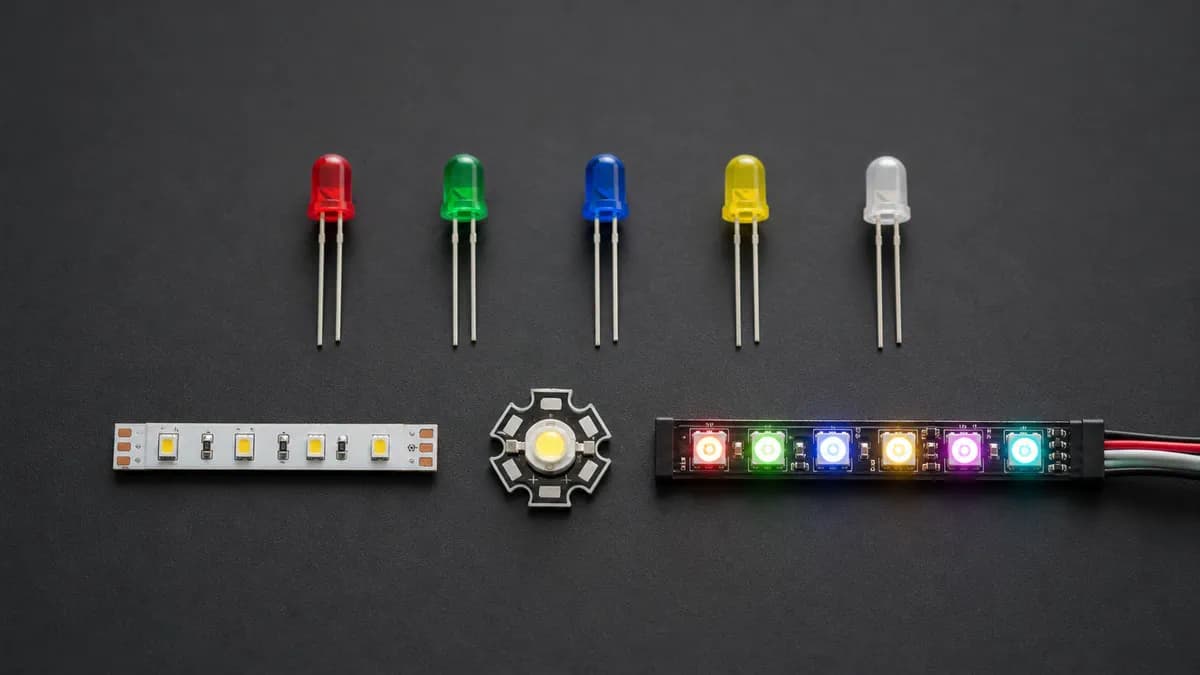
Through-hole indicator LEDs
3 mm, 5 mm, and 10 mm parts are easy to solder and inspect. Diffused lenses make broad, even indicators. Clear lenses produce stronger on-axis intensity. A 5 mm LED at 5–10 mA is usually enough for a panel indicator, so do not assume the familiar 20 mA value is mandatory.
SMD LEDs
0402 and 0603 packages save board space but are difficult to hand-solder. 0805 and 1206 are friendlier on a first reflow or hand-assembly job. Packages such as 2835, 3528, 5050, and 5630 describe approximate package dimensions, not a guaranteed optical output. A 5050 can contain three dies, which makes it common for RGB, but current and thermal limits still depend on the actual part.
High-power LEDs
1 W, 3 W, and 5 W LEDs commonly sit on a star-shaped aluminium MCPCB or another thermally managed carrier. They draw hundreds of milliamps to several amps. Use a constant-current driver and a heatsink, with no exception for a quick test beyond a few seconds. A bare power LED can exceed its junction temperature before the outside feels hot.
RGB LEDs
A four-pin RGB LED can have a common anode or common cathode. The three colour dies need three current paths and three PWM channels. RGB mixing can produce white, but it often has poor colour rendering because three narrow peaks do not fill the spectrum like a phosphor-converted white LED.
Addressable LEDs
WS2812B and NeoPixel-compatible parts combine an RGB LED and controller. They use a 5 V supply and a single 800 kHz data line with timing-sensitive pulses. SK6812 parts use a similar family of protocol, and SK6812-RGBW adds a dedicated white die, which is more useful than mixing RGB to make warm or neutral white.
APA102, SK9822, and HD107S use separate data and clock lines. They are less timing-critical and can refresh at high rates, which helps persistence-of-vision projects and camera work. WS2811 uses an external controller and is common in 12 V strips where one controller drives groups of three LEDs.
For a strip installation, put a 300–500 Ω resistor near the data input, a 1000 µF electrolytic across 5 V and ground at the strip, and a level shifter between a 3.3 V MCU and 5 V data when needed. Inject power every 1–2 m on a long run, sized for the strip current. Data ground, controller ground, and power-supply ground must share a reference.
IR and UV LEDs
850 nm IR is more visible to many cameras but can show a faint red glow. 940 nm is harder for cameras to see and is common in remote controls. A 365 nm UV LED produces more genuine ultraviolet excitation; 395 nm parts look violet and often leak visible purple light. Treat both as optical hazards.
Display formats
7-segment displays are built from LED segments and come as common-anode or common-cathode parts. Multiplexing lights one digit or row at a time, so peak segment current and duty cycle matter. Dot matrices, bar graphs, and alphanumeric displays use the same ideas with more switching channels.
LED strips
12 V and 24 V strips are usually constant-voltage products with resistors or current-control sections already distributed along the strip. 5 V addressable strips need a controller and more careful injection. Follow the cut marks. At the same power, 24 V strips carry less current than 12 V strips, so long runs usually suffer less voltage drop.
Filament LEDs
Filament LEDs contain a series of small dies along a phosphor-coated rod. Many are packaged into mains-style lamps with a driver inside the base. The visible filament does not mean the circuit can connect directly to a low-voltage battery or GPIO.
Where OLED and micro-LED differ
OLED pixels use organic electroluminescent layers and can be individually emissive without a separate LED package. Micro-LED displays use microscopic inorganic LEDs transferred onto a panel. Both are display technologies; a 5 mm indicator or WS2812B pixel is a packaged component with very different electrical and thermal constraints.
Heat: The Thing That Actually Kills LEDs
Junction temperature, Tj, is the real limit. Current determines electrical input, but the die temperature determines long-term degradation. LEDs do not throw heat away through radiation as efficiently as an incandescent filament. The heat must conduct out through the package.
In a power LED the path is die, substrate, solder joint, MCPCB, thermal interface material, heatsink, and air. Every interface adds thermal resistance. A 1 W LED needs a heatsink, a 3 W LED needs a real one, and a larger array may need airflow. Indicator LEDs at 20 mA normally dissipate only tens of milliwatts and need none of this.
Heat reduces light output and accelerates phosphor and encapsulant ageing. Lighting products often publish L70 or L80 life estimates, meaning the time until output reaches 70% or 80% of its initial level under a defined test. LM-80 is a test method for measuring lumen maintenance of LED packages or modules. These figures are meaningful only with the temperature and drive conditions that produced them.
Light Measurement and Colour Quality
Lumens measure total visible light output. Candela measures intensity in a direction. Lux measures lumens arriving per square metre. Think of a bare bulb, a focused torch, and a workbench: the bulb can emit many lumens in all directions, the torch concentrates candela into a cone, and lux tells you how much of that cone reaches the bench.
Indicator LED datasheets often use millicandela because the viewing angle is part of the product’s purpose. Lighting products use lumens because total output is more useful. A narrow 500 mcd indicator can look brighter straight on than a wide-angle part with higher total output.
Correlated colour temperature, or CCT, describes white appearance: about 2700 K is warm, 4000 K is neutral, and 6500 K is daylight-like. CRI, written as Ra, describes how naturally colours appear under the source. R9 is the deep-red test component, and a lamp can advertise high general CRI while still rendering reds poorly if its R9 score is weak.
Binning is the sorting of LEDs by measured wavelength, flux, and sometimes forward voltage. Two white LEDs from different bins can look visibly different even if both are labelled 4000 K. For a consistent product, buy by bin code and keep reels from the same lot together.
Troubleshooting: Symptom to Cause
Nothing lights: check polarity, the resistor path, the ground connection, and the solder joints. A dead LED is possible, but reversed polarity is more common. Use diode mode at the component before blaming the microcontroller.
Very dim: the resistor may be too large, the supply may not have enough headroom above Vf, or the MCU pin may be current-starved. Measure voltage across the LED and resistor while powered. The readings tell you which part is taking the voltage.
Lit once, then dead: suspect missing current limiting or reverse voltage above the LED’s often-low 5 V rating. A reverse-connected LED can fail even if the forward direction was never tested.
Flickering: look for a loose connection, supply sag, a low PWM frequency, or a floating control input. Addressable strips add data integrity and shared-ground checks.
Colour shifted: an overdriven die can change output as it heats. Phosphor degradation also changes white LEDs over time. Reduce current and improve the thermal path before replacing the part.
The first few addressable pixels work, the rest do not: check the data direction, signal level, resistor placement, and the pixel immediately before the dark section. One damaged pixel can stop the data chain.
The whole strip flashes random colours: the supply may be undersized, the ground may not be shared, the data line may be noisy, or the bulk capacitor and data resistor may be missing. Measure the supply at the far end while the strip is bright.
Random assembly failures: consider ESD, especially with blue, white, and UV InGaN parts. Use a grounded mat or wrist strap, avoid touching dies and leads unnecessarily, and store sensitive parts in proper packaging.
Five Circuits You’ll Actually Build
- Battery indicator: use a 3 V coin cell, a red LED, and a resistor sized for the coin cell’s limited current. The LED may be dim, but the circuit will be kinder to the cell than a 20 mA assumption.
- MCU status LED: connect a GPIO through 220 Ω to a red or green LED, then to ground. Start with a 5–10 mA target and confirm the pin’s recommended-current table.
- 12 V strip switch: connect the strip positive to 12 V and switch its negative with a logic-level AO3400. Tie MCU ground to supply ground, and keep the MOSFET gate low with a pulldown.
- ESP32 and WS2812B: provide a regulated 5 V supply, a shared ground, a 74AHCT125 level shifter, a 300–500 Ω data resistor, and a 1000 µF capacitor across the strip input. Inject power farther down a long strip.
- 3 W power LED: use a constant-current driver, mount the LED to a suitable heatsink with the recommended thermal interface, and check Tj rather than judging by the case temperature.
Buying LEDs Without Getting Burned
Demand a datasheet. If a listing has no manufacturer, part number, forward-current condition, or optical specification, treat its wattage and brightness claims as unverified. A “3 W” LED may contain a 1 W die, or it may only reach 3 W with a short pulse and aggressive cooling.
For addressable parts, check the exact controller family and timing requirements. Counterfeit or clone WS2812B parts can have different reset timing and voltage behaviour. For strips, check LEDs per metre, copper weight, cut spacing, IP20/IP65/IP67 construction, rated current, CCT, CRI, and the power-injection plan before ordering the length.
For a discrete LED, record Vf at the current you plan to use, the maximum current, viewing angle, wavelength or CCT, bin code, and package. That small checklist prevents most unpleasant surprises.
Safety Notes
Do not stare into high-power or focused LEDs. Blue-rich sources can create a photochemical retinal hazard, and IR is especially dangerous because it may not look bright enough to trigger a blink. Use diffusers, current limits, and appropriate protective eyewear for high-output work.
UV needs extra care for eyes and skin, particularly around 365 nm. Mains LED circuits and capacitive-dropper designs are not isolated from the supply. Treat the entire board as live unless a correctly designed and tested isolated supply separates it. IEC 62471 groups lamps by photobiological risk; use it as a safety reference, not as a substitute for guarding an exposed source.
FAQ
Can I connect an LED directly to a battery?
Only when the source itself limits current, such as a properly designed coin-cell application with a very low-current LED and a datasheet-backed check. For ordinary AA packs, USB supplies, 9 V batteries, and Li-ion cells, use a resistor or current driver.
What resistor do I need for a 5 V LED?
“5 V LED” usually means a module that already contains a resistor. For a bare LED, use its actual Vf and target current: R = (5 − Vf) / If. For a red LED at 2.0 V and 10 mA, 300 Ω is the calculated value, so 330 Ω is a safe standard choice.
Why did my LED burn out immediately?
The most likely causes are no current limiter, reversed polarity with excessive reverse voltage, or a shorted resistor. Measure the circuit without the LED first, then measure the resistor and LED voltages under power.
Do LEDs work on AC?
They conduct mainly in one direction. Low-voltage AC can drive an LED through a series resistor and a reverse-protection diode, or through a pair of inverse-parallel LEDs. Mains AC requires isolation and a properly rated driver.
Can I run LEDs in parallel without individual resistors?
Do not do that with ordinary LEDs. Forward-voltage mismatch makes current sharing unpredictable. Use one resistor per branch or a current-regulated multi-channel driver.
What’s the difference between WS2812B and APA102?
WS2812B uses a single timing-sensitive data line. APA102 uses separate data and clock lines, so it is easier to drive at high refresh rates and in projects where timing jitter matters. Choose based on wiring, cost, library support, and camera or POV requirements.
How long do LEDs actually last?
The die can last many tens of thousands of hours, but the useful answer depends on junction temperature, drive current, phosphor, solder joints, and driver quality. Read the product’s L70 or L80 data and its test temperature rather than trusting a generic lifetime number.
Why is my LED strip dimmer at the far end?
Resistance in the strip’s copper traces causes voltage drop. Feed power at both ends or inject it every 1–2 m on long runs, use heavier conductors, and choose 24 V where the product and controller support it. Measure voltage at the far end while the strip is loaded.
Conclusion
Three rules prevent most LED failures. Control current, do not assume a voltage source will do it for you. Treat heat as the long-term enemy of light output and lifetime. Read the datasheet, especially the forward-voltage test condition, recommended current, absolute maximum, reverse rating, and thermal notes.
Once those habits are in place, the rest is straightforward: pick the package for the job, calculate the resistor or select the correct driver, and verify the circuit with a meter before fitting the final parts. Browse Electronixity’s resistor, addressable LED strip, ESP32, MOSFET and transistor, and heatsink ranges when you are ready to build.